Designing gears in Autodesk Fusion 360 can be both engaging and simplified into clear steps. To kick off, start by importing gears directly from the McMaster-Carr catalog using the Insert menu. Next, choose the Gears category and filter your options based on key parameters such as pressure angle and material type. Once you’ve found a suitable gear, save it to your current design workspace. After that, personalize your gear by modifying its shape or adding features like mounting holes through sketches and extrusions. Finally, test how your gear interplays with other components to assure they mesh correctly for optimal performance in your project.
1. Insert Gears from McMaster-Carr
The easiest way to design gears in Fusion 360 is by importing them directly from the McMaster-Carr catalog. To start, open Fusion 360 and navigate to the Insert menu, then select Insert McMaster-Carr Components. A dialog box will appear, allowing you to search for various components. By typing “gears” into the search box, you can access a wide range of gear options available in the catalog. This method streamlines the design process, saving you time and effort in manually creating gear geometry from scratch.
2. Choose the Gear Category
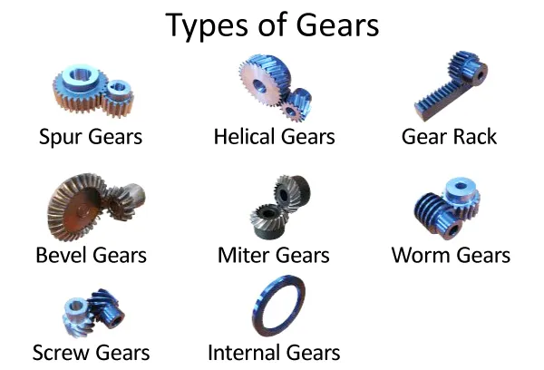
 Credits: khkgears.net
After accessing the McMaster-Carr catalog, the first step is to select the appropriate gear category. This allows you to focus on the specific type of gears you need for your project. You will find various categories like spur gears, bevel gears, and worm gears. Depending on your application, each type of gear serves a unique purpose. For example, spur gears are commonly used for simple rotary motion, while bevel gears are ideal for changing the direction of motion at a right angle. Once you’ve identified the category, you can further refine your search by applying filters based on specific parameters such as pressure angle, number of teeth, and material. This targeted approach not only saves time but also ensures that you find the most suitable gear for your design.
3. Filter Gear Search Options
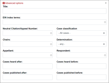
 Credits: ein.org.uk
To effectively narrow down your gear selection in Fusion 360, it’s essential to use the filter options wisely. After you’ve accessed the McMaster-Carr catalog, you can set specific parameters that align with your design requirements. For instance, if you need a gear with a pressure angle of 14.5°, you can specify that directly in the filter settings. Similarly, if your project demands a gear with 24 teeth made from nylon and with a pitch diameter of 1 inch, entering these details will streamline your search results. This targeted approach not only saves time but also ensures you find a gear that meets the exact specifications needed for your project. Filtering by material is particularly important if you have specific durability or weight considerations in mind. By adjusting these parameters, you can quickly hone in on the ideal gear component, making your design process more efficient and effective.
4. Save the Gear to Your Design
To save the gear you just imported, proceed with the following steps. First, click on the product number of the gear you want to use. This will direct you to the Product Detail page. Here, scroll down to find the 3-D Step option. When you select this option, it allows you to download the gear in a format suitable for Fusion 360. Make sure to click Save to import the gear model into your current workspace. Once saved, the gear will appear as a component in your design, ready for further modifications or integration into your assembly.
5. Modify the Imported Gear
Now that you have your gear in place, you can customize it to better fit your project requirements. Start by using the Delete key to remove any geometry that is unnecessary for your design. If your modifications involve adding holes or features, it’s important to first delete any chamfers or fillets that may interfere with your changes. This will ensure that your modifications are clean and precise.
For instance, if you want to add a specific hole pattern for mounting, first remove any existing features that might obstruct your design intent. This step allows you to tailor your gear to your specific design needs. After making these adjustments, you can proceed to create any additional features that will enhance your gear’s functionality.
6. Create Mounting Holes in the Gear
To add mounting holes to your gear, start by creating a sketch on the top face of the gear. Use the circle tool to draw circles where you want the holes to be. If your design requires multiple holes, you can use the circular pattern tool to evenly space them around the center of the gear. Once the sketch is complete, finish it and select the Extrude feature. Choose the circles you just created and set the operation to Cut. This will remove material from the gear, forming the mounting holes. Make sure to check the dimensions of the holes to ensure they fit the intended screws or fittings.
7. Summary and Testing of Gear Functionality
With your gear designed, it’s essential to test its function to ensure it performs as expected in your project. Start by using the Joint feature in Fusion 360 to simulate how the gear interacts with other components in your assembly. This allows you to visualize the movement and ensure that your gears will mesh properly once printed. For example, if you’re designing a gear train, confirm that each gear rotates freely without binding.
Testing should also include evaluating the gear’s fit within its intended application. Check for any potential interference with surrounding components or the housing. If necessary, make adjustments to the gear dimensions or positions to achieve a smooth operation. Additionally, consider creating a simple prototype using a low-resolution 3D print to physically test the gear’s functionality before committing to final prints. This hands-on approach can help identify any issues that may not be apparent in the simulation.
8. Additional Tips for Successful Gear Design
When designing gears in Fusion 360, there are several key factors to keep in mind to ensure effective and functional designs. First, avoid undercut by maintaining at least 13 teeth on your gears; this will help to reinforce the structure and improve durability. Additionally, remember to incorporate backlash, which is a small clearance between the gears. This allows for smoother operation and prevents binding during rotation. It’s also essential to consider the thickness of your gears. A thicker gear tends to be stronger and can handle more stress, but be mindful of added weight that could affect the overall assembly. For instance, if you’re designing a gear for a lightweight robotic arm, you might opt for a thinner design while still ensuring it meets the required strength. Lastly, always simulate the gear interactions using the Joint feature to check for proper meshing and functionality before finalizing your design.
- Understand the gear ratios and how they affect speed and torque.
- Use high-quality materials to ensure durability and performance.
- Check the compatibility of the gear with other components in your design.
- Pay attention to backlash, which can affect the precision of gear interaction.
- Consider the manufacturing process when designing gear sizes and features.
- Test your gear designs in simulation before physical prototyping.
- Regularly refer to technical specifications and standards for gear design.
Frequently Asked Questions
1. What is Fusion 360 and why should I use it for designing gears?
Fusion 360 is a powerful design software that combines CAD, CAM, and CAE tools in one platform. You should use it for designing gears because it offers advanced modeling features and easy-to-use tools that help create precise gear designs.
2. Can I design different types of gears using the same method?
Yes, you can design various types of gears, such as spur gears or bevel gears, using the same simplified method. The steps explained can be adapted for different gear types with minor adjustments.
3. Do I need any special skills to start designing gears in Fusion 360?
Basic knowledge of Fusion 360 is beneficial, but you don’t need to be an expert to start. The simplified method breaks down the process into manageable steps, making it accessible for beginners.
4. What are the key steps involved in the 7-step method to design gears?
The key steps include setting up your workspace, creating the gear shape, specifying dimensions, adding features, preparing for 3D printing or manufacturing, and finally, reviewing your design for any adjustments.
5. Is it possible to print the gears I design in Fusion 360?
Absolutely! Once your gear design is complete, you can export the model and use a 3D printer or manufacturer to bring your gears to life.
TL;DR This blog post outlines a simplified method for designing gears in Fusion 360 using a 7-step approach. It covers how to insert gears from McMaster-Carr, choose the appropriate gear category, filter search options, save the gear to your design, modify it, create mounting holes, and test the gear functionality. Additionally, it provides tips for successful gear design, ensuring effective and efficient project outcomes.

